Blog – When Sight Gauges Can't Live Up to Their Name
Even in industrial process control, seeing is believing. For all the value that control instrumentation provides in automating systems and physically taking operators out of the process, there are still plenty of applications where first-hand interaction with a system is ideal. Reading tank levels, seeing flow in piping, checking for entrained air and foam, gauging color and turbidity - all of these types of low-tech process steps need only a pair of eyes and a vantage point into the system, saving cost and complexity. In most cases, process components called Sight Gauges and Sight Windows are installed onto vessels and piping, allowing operators to peer through their clear windows to see into the processes behind. The problem is, these sight gauges are notorious for failing to perform their one key function of being transparent and allowing clear visibility. When such a simple component is so prone to failure, it becomes apparent that a better solution is needed, and we've got just the right alternative: Mechanical Process Indicators.
To begin, let's understand the problems that Mechanical Indicators are designed to solve.
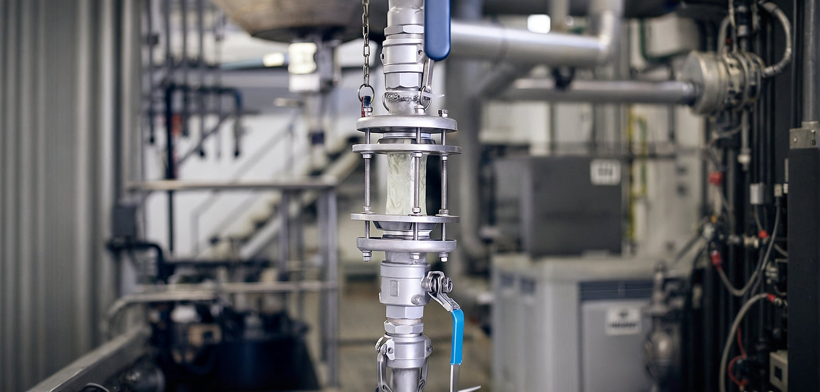
Sight gauges are a class of process piping components that provide a clear window directly into an operating process. Sight gauges come in two general styles: level gauges and flow gauges. Sight level gauges are installed on the sidewalls of vessels so that liquid levels can be directly seen. Sight flow gauges (as seen below) are installed in pipelines so that liquids being conveyed can be seen as well. In both cases, the objective of a sight gauge is to quickly determine if a liquid is present and if there are any unexpected conditions that operators must react to.
Sight gauges seem simple enough, but many specific issues plague sight gauges and always worsen over time:
- Installation Position - Sight glasses must be installed in a location that operators can physically get to (both to view and to clean/maintain), typically up close to a process vessel or line. This limits where and how they can be utilized.
- Visibility - Second to the above point, sight glasses must be installed at a usable viewing angle (especially level gauges), shielded from reflections, and not overly dark or bright. Further, many fluid properties make reading a sight glass difficult, such as with high viscosity fluids that smear the glass and present false-positive readings.
- Physical Wear - Sight glasses are very sensitive to physical abrasion and thermal stresses that, over time, can scratch, pit, and crack the glass.
- Discoloration - Many process fluids can attack and discolor sight glasses, staining the glass and making readings difficult. Thermal cycling and UV exposure can also lead to the same problems.
- Chemical Corrosion - Aggressive fluids often induce a chemical reaction with sight glass materials, which can equally lead to material discoloration and physical degradation.
- Safety - Sight gauges place a piece of plastic or mineral material between operators and a potentially hazardous process, which presents inherent risks of exposure to high pressure, high temperature, chemical, and otherwise hazardous conditions should the glass fail.
For some applications, sight gauges are just fine. But for anything beyond gentle, low-risk, non-hazardous, small-scale applications, a more resilient Mechanical Indicator option is very likely better suited, as we'll see next.
Getting to Know Mechanical Flow and Level Indicators
Mechanical Indicators are available in two forms: flow indicators and level indicators. Both styles are fundamentally designed to solve the many challenges of sight glasses through these common features:
- Mechanical, Not Visual Read-Outs - Mechanical indicators utilize physical probes to contact process media and displace a rotary indicator dial that operators can see. This eliminates the need to peer through obscured glass to see the process media directly.
- Physical Separation of Process and Operator - Mechanical indicators consist of two separate chambers, with one containing the process-contact probe and one containing the rotary indicator dial. These two chambers are 100% physically separated, using a magnet on the end of the wetted probe to influence the dial. For this reason, operators are completely protected from leaks and blow-outs.
- Superior Visibility - Mechanical indicators utilize a high-visibility dial which plainly shows red or green color bands, communicating unmistakable feedback to operators even in indirect, sunny, far-off positions. No need to get up close to the indicator or pull out a flashlight to peer through a sight glass into the fluid chamber within.
Now let's take a closer look at mechanical flow and level indicators individually.
Flow Indicators
Mechanical flow indicators are intended for installation in pipelines and will switch between low-flow and flow-present conditions. A mechanical flow indicator is constructed using a wetted flag and a target disc that the flowing fluid presses against.
When fluid flows into the target, it rotates the flag, which in turn magnetically rotates a dual-color roller dial in the separate read-out chamber. When the flow falls below the indicator's switch rate, the dial will present its red side. When the flow increases over the indicator's switch rate, the dial will present its green side. Flow indicators can be calibrated to 1.5 GPM or 5 GPM switch rates.
|
Fig. 1 - Mechanical Flow Indicator Features |
Fig. 2 - Mechanical Flow Indicator Operation |
Level Indicators
With a very similar operation to the above flow indicator, mechanical level indicators are intended for installation in fluid vessels and are used to indicate the presence of fluid within the vessel at particular elevations. Level indicators use sealed floats instead of flags, and these floats will rise and lower as they interact with changes in fluid.
When the vessel's fluid level rises, the float will be raised with it and will switch the roller's color to green, signaling the presence of fluid at or above the elevation of the indicator. When the vessel's fluid level falls, the float will drop and will switch the roller's color to red, signaling a low level below the elevation of the indicator. Mechanical level indicators are usable with fluid specific gravity values of 0.4 SG and above.
|
Fig. 3 - Mechanical Level Indicator Features |
Fig. 4 - Mechanical Level Indicator Operation |
Selecting Mechanical Indicators for Their Ideal Application Benefits
Mechanical indicators are wonderful options for a wide range of process systems and media, but do perform best when they're selected for the following ideal application goals:
- Low Viscosity, Clean Fluids - Since mechanical indicators rely on free, consistent movement of an internal probe, their motion can be impaired by fluids that are overly viscous (thick) or that contain large particulates. As such, mechanical level and flow indicators are best when used with low viscosity, non-coagulating, free-draining fluids that have minimal suspended solids.
- Long, Minimal Maintenance Life - All else equal, mechanical indicators require much less maintenance and cleaning than sight gauges since they have no glass needing to be wiped off, scrubbed, or replaced. Over time, the indicator's wetted probe only needs periodic cleaning to remove any build-up on the probe, should it induce drag and sluggish switching.
- Locations Without Electricity - Many applications only need visual operator inspection, but can't use sight glasses due to the risk factors mentioned earlier. In these cases, the next typical solution would be to install powered level or flow switches tied to a light or audible beacon. Mechanical indicators provide a great in-between alternative, eliminating sight glass risks without the added electrical service.
- Hazardous Processes - Mechanical indicators solve many problems inherent with hazardous process systems, defending against corrosivity, extreme temperatures and pressures, chemical reactions, and combustible/flammable conditions thanks to their fully sealed, magnetically separated wetted and dry chambers.
---
For over 40 years, Thomas Products has served industrial customers through the manufacture and supply of specialized fluid flow, level, pump control, and sight glass instrumentation. Our Bristol, CT, manufacturing campus produces American-made sensors in strict alignment with our veteran ownership's principles of tireless dedication, rigorous standards of quality, and faithfulness to our values and mission. Thomas Products welcomes your direct inquiries for both standard and custom applications via our website at https://thomasproductsusa.com, by email at sales@thomasprod.com, or by phone at (800) 666-9101.


